
[ad_1]
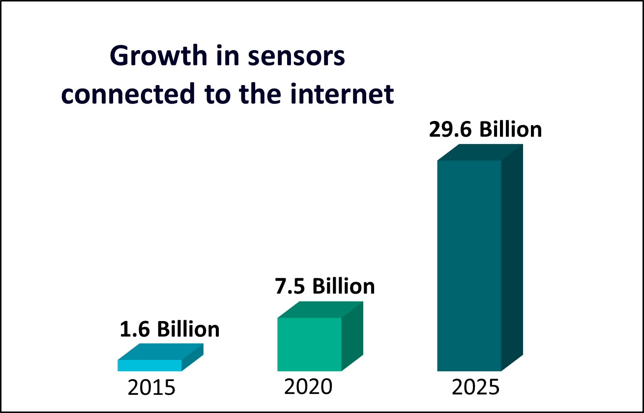
The proliferation of electronics in our lives is visible almost everywhere on the planet, even in the most remote locations and among the most remote communities. Most of us who live in industrialized societies see the impact daily, from cell phones to laptops to our automobiles and businesses, but from anywhere on earth, you can see satellites and space stations crossing the sky. Even in nomadic and agrarian societies that most of us would not associate with electronics, cell phones are being used to improve crop yields and perform business transactions [1,2,3].
Typically, the most in-demand features in new mobile and so-called “edge” electronics [4,5], other than improved battery life, are new sensors. In 1980, electronics contributed about 10% of the total cost of a car. By 2010, that percentage reached 35%, and by 2030, it’s projected to be close to 50% [6]. A multitude of sensors are required in today’s cars to make them safer, provide driver assistance, and provide entertainment. These edge devices combine sensors and computation, which means mixed signal design—that is, both analog and digital functionality on a chip.
Design flows for both analog and digital integrated circuit (IC) designs are very mature, and continue to become more sophisticated every day. On the digital side, there are a wide variety of electronic design automation (EDA) verification tools and flows for physical, electrical, and reliability verification that ensure the final design sent to the foundry fully complies with the physical requirements necessary to manufacture a chip that functions in the field for many years to come.
While physical and electrical verification is also well-established for analog designs, reliability verification for electromigration (EM) and voltage (IR) drop still struggles with the challenge of full chip verification[7]. Existing EM/IR tools are dependent on the capacity of SPICE tools, which ultimately limits their capacity to provide detailed verification of the operation of a chip that includes and accounts for all the parasitics involved in the actual implementation of the design. When a design exceeds a few million transistors, design teams often resort to a variety of custom-built solutions to get a “good enough” estimate of the EM and IR performance of their full design. Because these methods worked for a very long time, and have enabled the industry to put millions of devices into production, it’s all good, right? Not anymore.
Changes in the semiconductor industry are making those previous approaches riskier to the point of jeopardizing the market success of the end product. One of the major factors that underlies many of these risk factors is the process technology used for these designs. Analog designs were historically targeted to older technologies for many good reasons, such as noise, device matching, and reliability. Analog in general was very happy at 180nm. The transition to 130nm to take advantage of copper (Cu) interconnects was so traumatic for many design houses that you still hear stories about it decades later. A decade after that came the push down to 90nm.
Today, many analog companies are being driven into the most advanced technologies so their analog circuit designs can feed data in and out of the digital processing units that make use of that data. Network processing chips must get data in and out, which means arrays of analog-to-digital converters (ADCs) and digital-to-analog converters (DACs). Any chip using remote connectivity requires some sort of analog communication—whether it is WiFi, Bluetooth®, or straight radio frequency (RF). In turn, this requirement means that if your chip needs to be a 3nm design to get the throughput you need, then your analog communication circuits must also be in 3nm.
So, what is the problem? Why the distress? These advanced (and even some of the not-so-advanced) technologies use smaller wires that are more susceptible to EM and IR drop. In addition, EM limits are an exponential function of temperature. One typical rule of thumb is that a circuit’s lifetime is cut in half for every 10° above 100°C. For example, a part designed for a 5-year lifetime at 100° would only have a real-world lifetime of 1.25 years at 120°. Of course, one way to improve the lifetime of a routing is to make it larger—but that requires more area. Silicon area not only costs more, but sometimes it’s just not available because the chip needs to fit in a certain socket or die area for the application.
Well, most circuits don’t operate in a 120° environment, so that’s not really a problem, right? Right, unless your circuit is in an automobile. The Class 0 automotive standard is <1 defective parts per million (DPM) at 150°C [8,9]. While not all electronics in an automobile must meet that strict standard, as we put more and more electronics in the drive train of vehicles (including electric and hybrid cars), there is a greater demand for electronics that meet these standards. Also, wearables and many edge devices must be designed to operate in hostile environments. I might find it annoying if my phone shuts off because I left it in the sun, but what if a tractor doesn’t navigate properly because the sensors in it stop operating halfway through a hot summer afternoon? That’s a business problem, not just a minor irritation.
The impact of temperature on EM also affects the most advanced designs—things like cell phones and internet infrastructure. To increase performance and reduce latency, some design companies have started stacking multiple die together in 2.5 and 3D arrangements in a single package. Shorter distances mean lower impedances, faster data rates, and…higher temperatures. An analog design that easily passed EM verification as a single die may no longer have an acceptable lifetime, or even function properly, in such an environment.
So, how do analog designers avoid these problems? Historically, there hasn’t been an accurate, reliable, or easy way to perform a comprehensive EM and IR analysis of large analog circuits. Once circuits exceed the capacity of SPICE tools, engineers must start pulling out subsets of the circuit to analyze individually, rely on a single operating point (direct current, or even static analysis), forego some of the analysis, or…just build it bigger and hope that it all works.
Fortunately, analog designers now have another option. In 2021, Siemens EDA introduced the mPower power integrity platform, which provides fast, accurate chip-level EM and IR analysis for even the largest analog and mixed-signal designs in a user-friendly tool suite. Specifically, the mPower Analog tool contains an innovative high-capacity (HC) dynamic analysis functionality—a simulation-based EM/IR analysis that can run on the largest, most complex blocks and chips to enable fast, accurate power integrity analysis of 5G sensors and other large, complex IC systems.
mPower HC dynamic analysis provides the detailed analysis designers need to confidently sign off designs for manufacturing, while enabling faster overall turnaround times by providing full-chip and array analyses from block-level SPICE simulations. It can also enable faster iterations early in the design cycle by using pre-layout SPICE simulations. With the mPower Analog tool, designers can analyze analog blocks and chips that they simply couldn’t before with existing tools.
MaxLinear, who produced the industry’s first 5nm PAM4[10] digital signal processors (DSPs), uses a variety of processes for their IC designs, including finFET, planar, and bipolar-CMOS-DMOS (BCD). They were facing multiple power verification issues in their traditional hierarchical EM process, including capacity limitations, too many constraints for the production environment, and accuracy issues when mapping schematic and custom layout devices. They implemented the mPower Analog solution for a 5nm DSP design, and found that it resolved these challenges while providing high accuracy in the results.
Because the mPower layout analysis is always flat, it eliminates most of the construction constraints associated with the traditional hierarchical EM analysis, allowing custom layout engineers to use their existing methodology. It also allows the reuse of existing silicon program intellectual property (IPs) without modification. Finally, by leveraging the Calibre nmLVS layout vs. schematic verification into the mPower flow, simulation results can be hierarchical. The use of Calibre nmLVS eliminates the need for hierarchical models and assumptions, while the capacity of the mPower engine enables full-chip analysis. After validating the mPower results against their reference flat EM analysis for small blocks, MaxLinear is now deploying the mPower tool suite for all of their 5nm designs.
onsemi was looking for an EM/IR solution for their complex mixed-signal image sensor designs. These designs require accurate solutions for analog and digital power analysis IR drop, and EM, but the incumbent tools had poor correlation to silicon, and were difficult to use consistently and reliably. While onsemi was interested in adopting the full mPower tool suite for both digital and analog power analysis, the unreliability of their current analog tool and the difficulty of using it made the features of the mPower analog tool particularly attractive:
- Scalable from the smallest to the largest circuits
- Supports both extracted view and DSPF flows
- Calibre RVE interface to Virtuoso enables link back to design environment
- Ease of use and simple integration into design flow
onsemi tested the mPower analog tool on a 110nm 2-Megapixel sensor design with 1.5M devices and 23M grid resistors, using the mPower analog static analysis functionality. Running with 16 threads and 31.5GB of memory, the mPower Analog run took 35 minutes to complete. Their evaluation of the process and the results confirmed the benefits of the mPower Analog solution:
- Accurate results with quick runtimes
- High capacity, fast design loading, stable display
- Helpful cross-probing feature
- Fast, early identification of grid weaknesses
- Flexible power assignment—by size, hierarchy, or regexp
They also tested the mPower Analog HC dynamic analysis feature on a 110nm design with 1.1M devices and 7.5M grid resistors. Running with 16 threads and 26GB of memory, the flow completed in 6 hours, 25 minutes. Total simulation time was about 6 micro-seconds, and generated 241,600 time-steps. With the mPower HC dynamic analysis feature, onsemi achieved multiple benefits:
- Accurate results on large blocks with minimal simulation time
- Ability to simulate smaller blocks once, then reuse
- Ability to assign windows and delays per sub-block instance
To evaluate the scalability of the mPower Analog tool, onsemi used it to perform dynamic EM/IR analysis on a 65nm design with 11.2M devices and 152M grid resistors. Running with 32 threads and 104GB of memory, the dynamic analysis run completed in 8 hours, 40 minutes, including 10 micro-seconds of simulation time. Previously, onsemi had never been able to perform dynamic EM/IR analysis on a full analog chip design.
After this extensive testing and evaluation, onsemi implemented the mPower toolsuite as part of their standard design and verification process flow. Their next step is to integrate the dynamic chip-level analog analysis with the digital analysis for a comprehensive chip-level power analysis flow.
Conclusion
Analog and mixed-signal IC designs are a critical and growing component of today’s electronics. Without the ability to run full-featured, scalable power analysis on these designs, design companies run the risk of poor performance or product failure in real-world use, with outcomes ranging all the way from customer dissatisfaction with consumer products to potential injury or death in mission-critical devices.
With the emergence of scalable power analysis solutions like the mPower tool suite, design companies now have proven full-chip power analysis solutions that deliver fast, accurate results using industry-standard formats, a user-friendly GUI, and tight integration into design environments. Analog, semi-custom, and digital power integrity analysis can be readily integrated into existing design flows while scaling to circuits and chips of any size, ensuring sensor reliability and performance in real-world use.
For more information, click here.
Author
 Joseph Davis is senior director of product management for Calibre interfaces and mPower power integrity analysis tools at Siemens Digital Industries Software, where he drives innovative new products to market. Prior to joining Siemens, Joseph managed yield simulation products and yield ramp projects at several leading semiconductor fabs, directing yield improvement engagements with customers around the world and implementing novel techniques for lowering the cost of new process technology development. Joseph earned his Ph.D. in Electrical and Computer Engineering from North Carolina State University.
References
[1] Quandt A, Salerno JD, Neff JC, Baird TD, Herrick JE, et al. (2020) Mobile phone use is associated with higher smallholder agricultural productivity in Tanzania, East Africa. PLOS ONE 15(8): e0237337. https://doi.org/10.1371/journal.pone.0237337
[2] N. T. Krell, S. A. Giroux, Z. Guido, C. Hannah, S. E. Lopus, K. K. Caylor & T. P. Evans (2021) Smallholder farmers’ use of mobile phone services in central Kenya, Climate and Development, 13:3, 215-227, DOI: 10.1080/17565529.2020.1748847
[3] Chhachhar, Abdul Razaque & Hassan, Md Salleh. (2013). The Use of Mobile Phone Among Farmers for Agriculture Development. International Journal of Scientific Research. 2. 95- 98. 10.15373/22778179/JUNE2013/31.
[4] William Wong, “Understanding Edge Computing,” Electronic Design. May 18, 2020. https://www.electronicdesign.com/technologies/embedded-revolution/article/21131720/understanding-edge-computing
[5] “Edge device,” Wikipedia. https://en.wikipedia.org/wiki/Edge_device
[6] Martin Placek, “Automotive electronics worldwide – statistics & facts, “ Statista, Sept. 23, 2022
https://www.statista.com/topics/7983/automotive-electronics-worldwide/
[7] Majeed Ahmad, “EDA Tools for Analog: Where Do I Go From Here?,” EE Times. January 12, 2023. https://www.eetimes.com/eda-tools-for-analog-where-do-i-go-from-here/
[8] “What is AEC-Q100 Qualification?,” everythingRF, Nov. 27, 2019. https://www.everythingrf.com/community/what-is-aec-q100-qualification
[9] Jeff Darrow, “What’s the Price Tag on Failure in Automotive Electronics?,” Electronics Design. June 5, 2019. https://www.electronicdesign.com/markets/automotive/article/21808089/whats-the-price-tag-on-failure-in-automotive-electronics
[10] David Maliniak, “ The fundamentals of PAM4,” EDN. Jan. 16, 2016. https://www.edn.com/the-fundamentals-of-pam4/
The post The Designer’s Dilemma: Everything is OK…Until It Isn’t appeared first on EE Times.
[ad_2]
Source link